A&A CORVETTE C5 SUPERCHARGER SYSTEM

INSTALLATION INSTRUCTIONS FOR THE C5 CORVETTE

A&A SUPERCHARGER FOR C5 CORVETTE

A&A CORVETTE PERFORMANCE C5 SUPERCHARGER

A&A CORVETTE PERFORMANCE C5 SUPERCHARGER INSTALLATION INSTRUCTIONS

GETTING STARTED


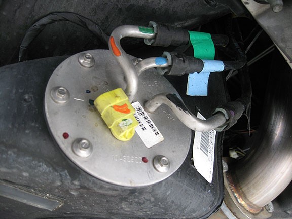
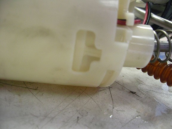
Proper installation of this supercharger kit requires general automotive mechanic knowledge and experience. Please browse through each step of this instruction manual prior to beginning the installation to determine if you should refer the job to a professional installer/technician. Custom PCM calibration based on specific vehicle and engine modifications will be required for use with this kit. A&A Corvette does not include custom tuning with supercharger kits. We can, however, provide you with a “Base” tune. (California cars running our CARB compliant system will receive an approved calibration from A&A.) This will allow the car will start with the large injectors and make the car drivable, so you can drive it to a dyno shop for custom tuning. Please contact A&A Corvette for more information. If you own a 1997-2002 model, you will be installing a new in-tank fuel pump. You will want to have as little fuel as possible in the tank before you start! Also, if you have a 1997-2002, you should change your power steering/alternator bracket to a later style, please see Section 3 of this manual for more information.


  • Raise the car on a suitable lift or jack stands. Make sure the steering wheel is locked in the straight forward position before starting. You will be disconnecting the steering rack from the steering shaft during this install. It is very important that the wheel NOT be turned while the steering rack is disconnected. The shaft will only go back on one way, but should the wheel be allowed to turn a full rotation it’s possible it could be reconnected. There is a wire “coil” inside the steering column that would be damaged if this were allowed to occur.

  • Disconnect the battery.

  • Remove plastic ignition coil covers.

  • Remove the battery shroud by taking out the two push pins holding it in. This will allow easier access to the spark plugs on the passenger side.
(REMOVE 2 PUSH PINS FROM BATTERY SHROUD)
  • Remove the (2) 10mm bolts holding the air injection line. This will allow for easier access to the spark plugs on the driver side.

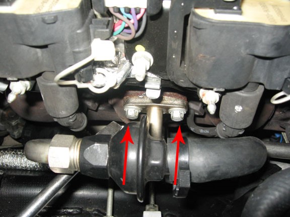
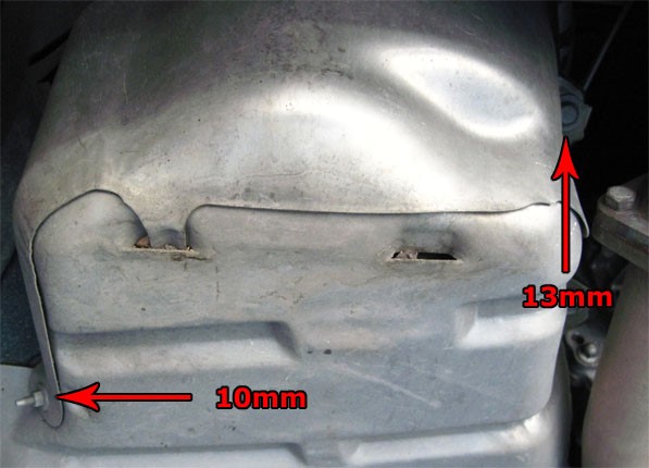
(REMOVE TWO 10mm BOLTS)

  • Remove all 8 spark plug wires and blow compressed air around spark plugs.

  • Remove factory spark plugs. Gap the provided TR6 plugs to .035” and install with -anti seize on the threads.

  • Bleed any remaining fuel pressure into a suitable container by depressing the Schrader valve at the end of the fuel rail. Make sure you catch or clean up any fuel that may escape. Blow compressed air on the manifold around the fuel injectors to clean out any debris in the area. Remove safety lock on fuel line at fuel rail side and remove fuel feed line at the fuel rail side using a disconnect tool. (Place a rag under fuel line to help absorb leaking gas.) Disconnect the injector harnesses by pushing “in” the release tabs and pulling on the connector. There is a positive wire going to the alternator that goes over the driver side fuel rail. Lift this wire by pulling up on the plastic connectors. Remove the 4 (10mm) bolts holding the fuel rail and gently pull up on the fuel rail and remove from the vehicle. Remove the injector retaining clips from the top of the injectors and remove injectors. Lightly grease the O rings on the injectors and replace them in the reverse order as they were removed. Reinstall the clips. Reinstall the fuel rail. NOTE: Leave the stock injectors in place if you plan to drive to a tuning shop for calibration. You can drive CAREFULLY without any ill effects with the stock injectors.

(FUEL RAIL BOLTS AND SCHRADER VALVE)

  • Loosen hose clamp at the throttle body to intake tube. Disconnect the Mass Air Flow Sensor (MAF) connector by removing gray lock and push tab in and pull gently. Remove the valve cover breather hose by using a flat screwdriver and pushing the gray tab into the connector. Pry up on the tabs located on the air bridge until released. Remove complete air filter assembly. If you have a 1997-2000 model, take the IAT sensor and grommet out and set aside, you will be reusing these later.

  • Unplug the hood light harness and the outside air temperature sensor. These are in the nose of the car looking down from the top of the motor.

(RADIATOR HOLD DOWN, SAME ON BOTH SIDES)

  • Remove accessory drive belt and the two bolts holding the tensioner to the water pump. Keep these bolts handy as they will be used to mount part of the rear supercharger bracket.

(TWO TENSIONER BOLTS ATTACHED TO THE WATER PUMP)

  • Remove the (5) 7mm bolts that hold the bottom bumper lip to the radiator shroud. 

  • Remove the (2) 7mm bolts up next to the radiator support bracket. There are two push pins that connect the top of the radiator shroud to the AC condenser. Pull the radiator shroud up out of the car.Take the metal clips off and set aside, you will be using these later. You will also be reusing 5 of the 7mm screws.

(REMOVE SEVEN 7mm SCREWS)

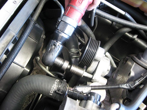
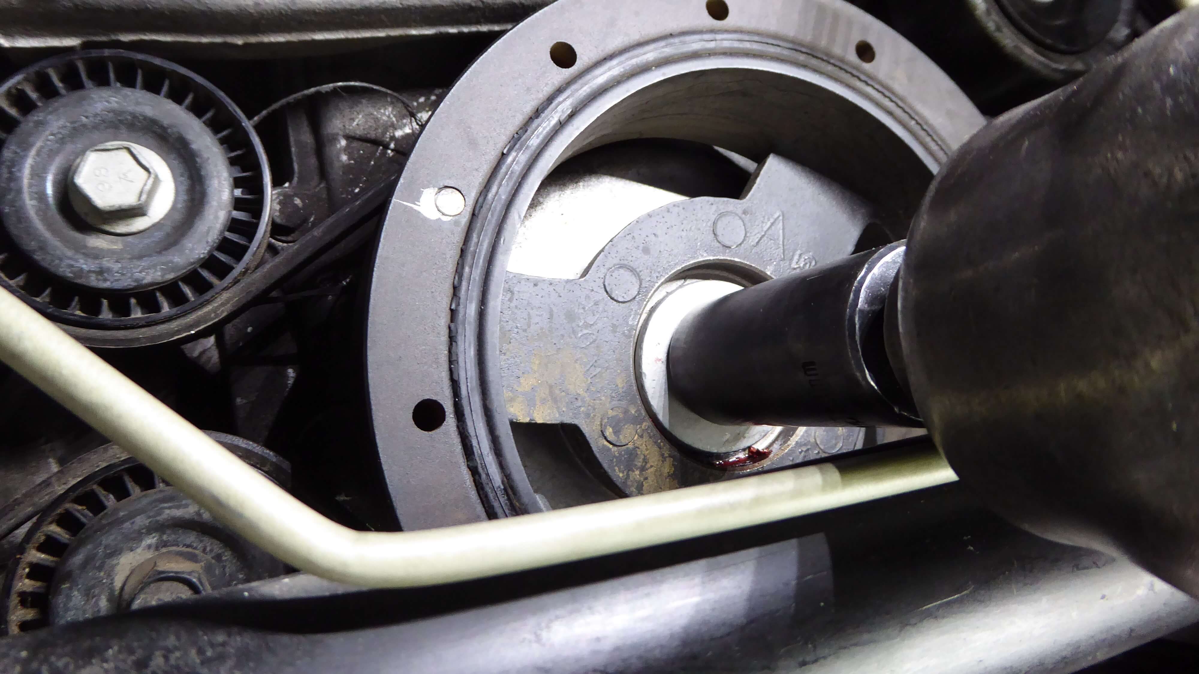
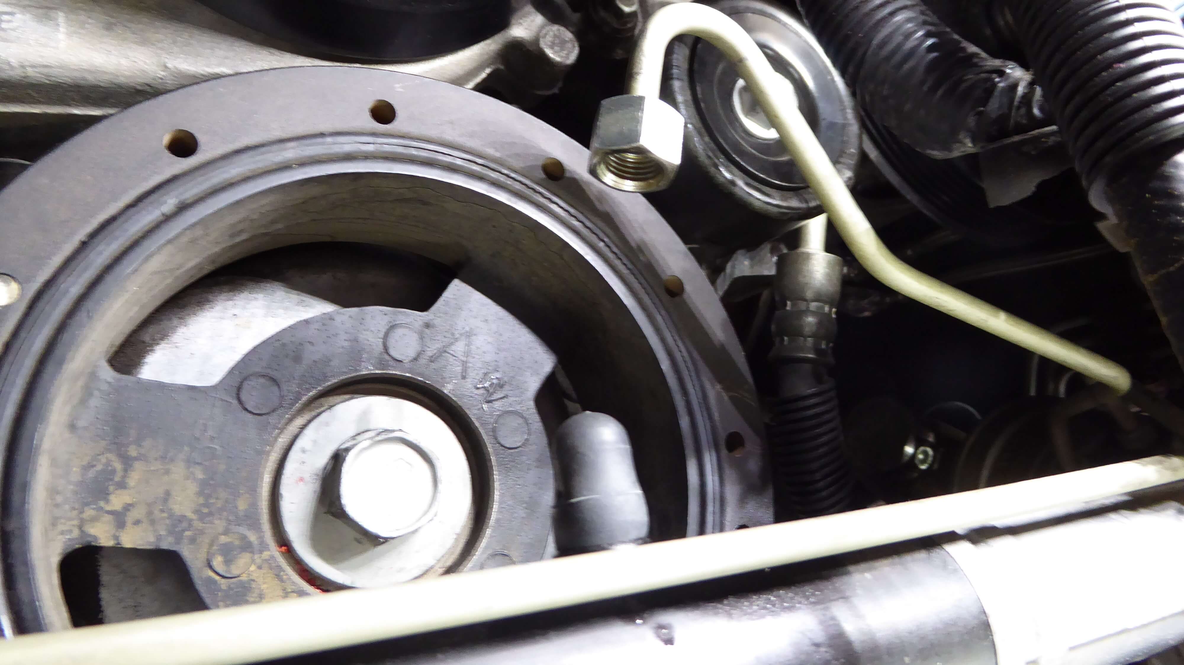
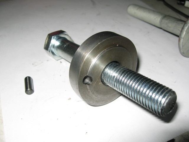
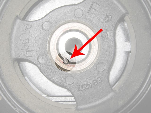
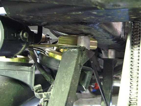
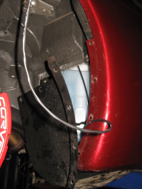
PINNING THE CRANKSHAFT PULLEY: THE STEERING RACK DOES NOT NEED TO BE REMOVED TO PIN THE CRANKSHAFT


  • The front sway bar needs to be dropped out of the way.

  • Remove the 4 (13mm) sway bar bolts at the sub frame and let the bar swing down out of the way.

(PASSENGER SIDE SWAY BAR BOLTS)

  • Remove the fan assembly. Disconnect the 4-pin connector coming out of the fan control module. Open all the wire loom connectors on the fan. Push the fan up and over the plastic brackets attaching it to the radiator and drop it down to remove it from the vehicle.

  • The ABS module bracket will need to be removed. Remove the two (depending on the year, you may have four) 13mm bolts holding the bracket to the frame. Loosen, but do not remove the three 10mm nuts holding the module to the bracket. 

(ABS MOUNTING BRACKET)

PLENTY OF CLEARANCE WITHOUT REMOVING THE STEERING RACK

  • Remove the two long 18 MM bolts that hold the steering rack to the frame. There are 18MM nuts on the back side, so you’ll need to hold them with a wrench in order to remove the bolts. The big ABS bracket can now be removed from the bottom. The module may now be pushed upwards to gain access to the steering rack. Pry the rack up and over to the driver side to release it from its mounts. Moving it over just an inch or two will suffice.
      
  • Now remove the two 18MM engine mount bolts facing straight down through the cradle. Use a piece of 2X4 to spread the load on a post jack (or similar) and lift the engine at the rear of the oil pan. 


LEFT

18mm STEERING RACK BOLTS


RIGHT

18mm STEERING RACK BOLTS

  • Some models have a hard line attached to the rack that is in the way. Simply disconnect it and bend it up out of the way as shown.
     
  • There is now ample clearance to get a socket and impact gun on the balancer bolt.

  • Remove the factory balancer bolt with a 24MM socket. A powerful impact gun works best. Insert the provided 24MM bolt through the pinning fixture and bolt it on in place of the factory bolt. Tighten it enough to ensure it won’t move around when drilling through it. Measure the provided pin and make sure you drill to a depth just slightly deeper than the length of the pin. Use a 1/4” drill bit and drill through the fixture, using the small hole in the fixture as a guide. It’s very important that the pin doesn’t protrude out beyond the edge of the balancer. The bolt will not seat and will get damaged if the pin sticks out beyond the lip on the balancer. Notice that the crankshaft is actually recessed into the balancer by about ¼”. (1/2” when using our 8 rib balancer) You do not have to have the pin flush with the end of the crankshaft. It’s the flat face on the balancer that is of concern. Remove the fixture, blow out any shavings and insert the pin in the hole you have just drilled. (Double check your depth first)

(PIN FIXTURE WITH BOLT AND PIN)

(DRILLING CRANK AND BALANCER THROUGH PIN FIXTURE)

(PIN INSTALLED IN CRANKSHAFT AND BALANCER)

  • Take the NEW provided factory balancer bolt, heat the threaded area with a hair dryer or heat gun, put red Loctite on the first 1/2” of threads and insert it in the crank. Tighten it to manufacturers’ specs. This bolt must be EXTREMELY tight. Heating it up expands the bolt slightly and helps with its retention once it cools down.

ALTERNATOR / POWER STEERING PUMP BRACKET

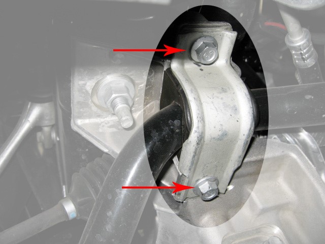
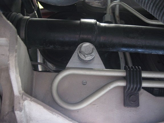
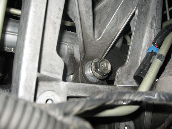
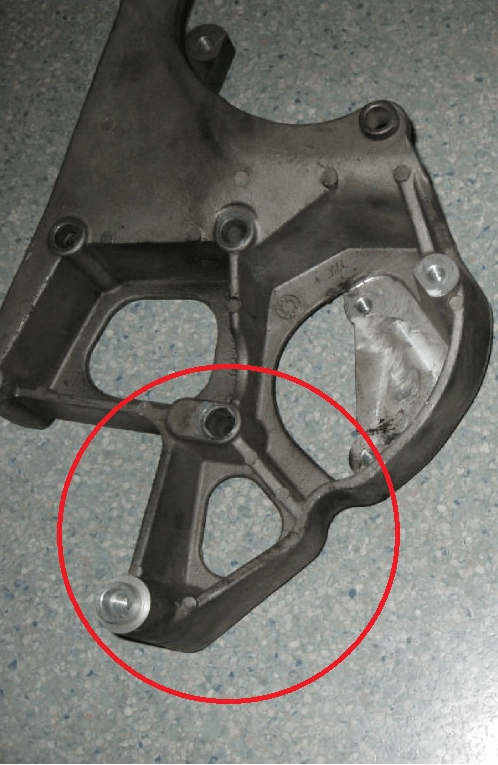
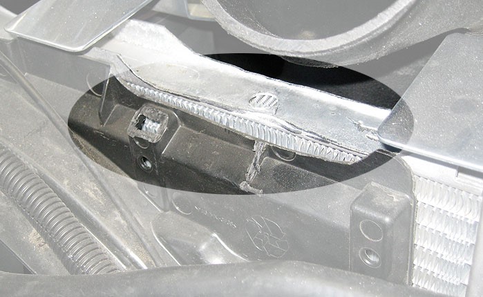
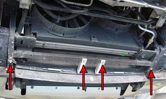
There are two styles of alternator power steering brackets. Chevrolet changed the design in 2003. The early style is very weak and prone to breakage. The new style is much stronger. They are about $120 at your dealer. We recommend you have the later style. (GM# 12578068) The following picture shows the difference. 


EARLY STYLE

Alternator Power Steering Brackets


LATE STYLE

Alternator Power Steering Brackets

(NOTE: This entire section applies ONLY to the standard “engine oiled” units. For V3 “self- contained” units, please go to step 5.)

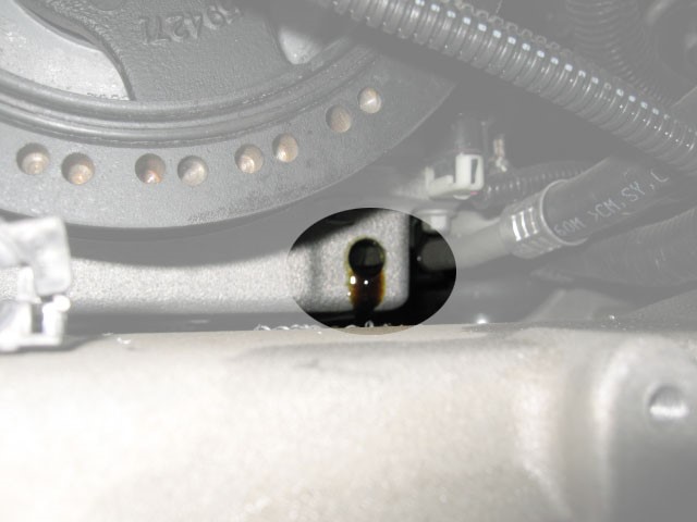
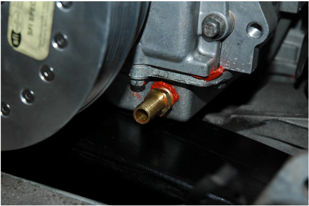
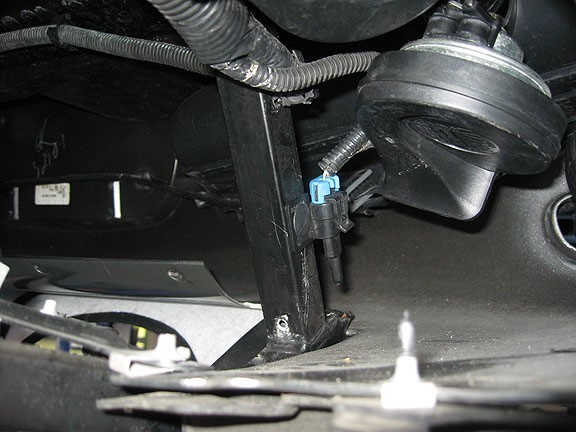
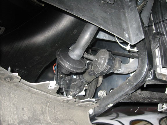
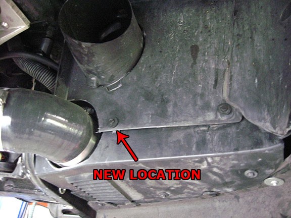
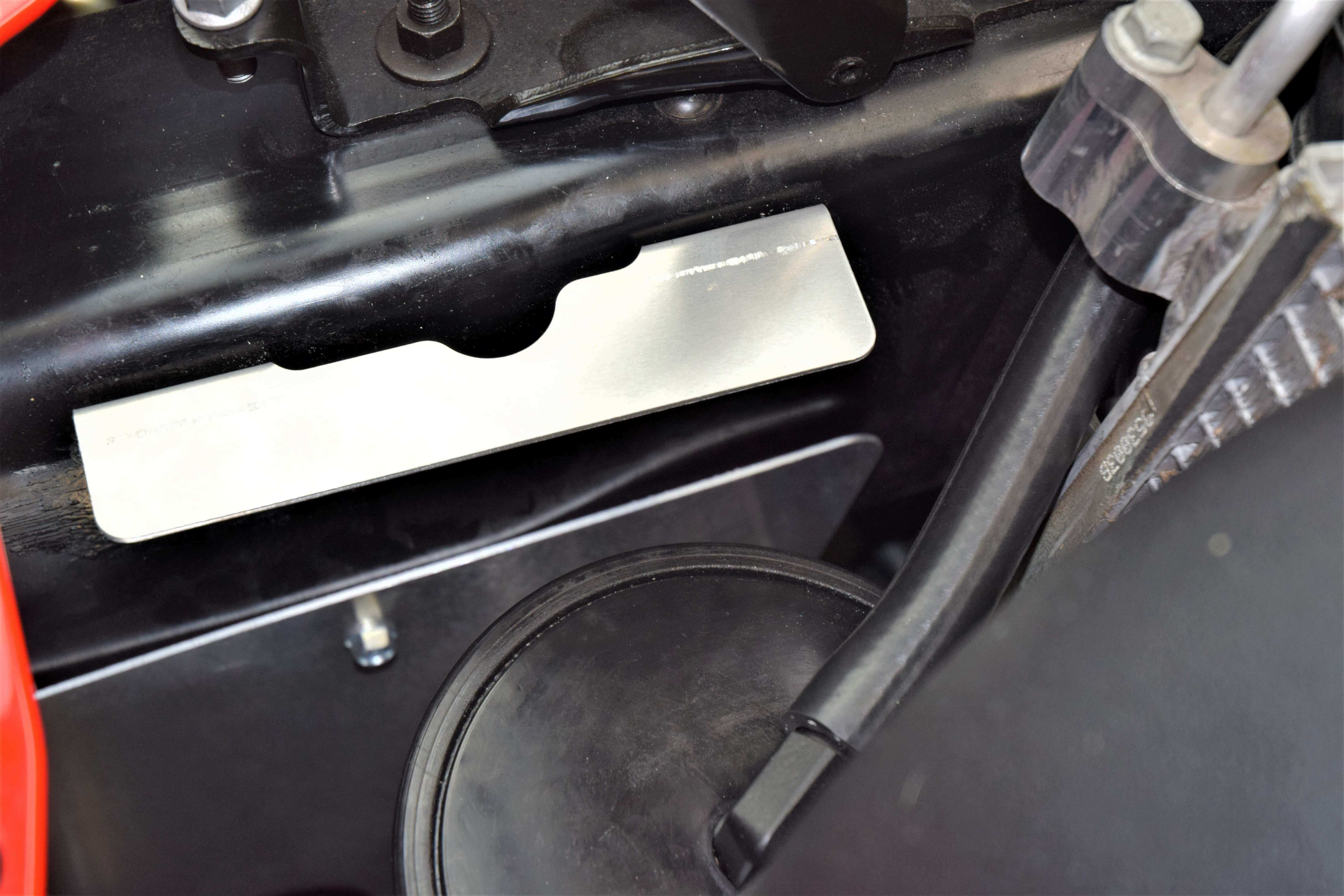
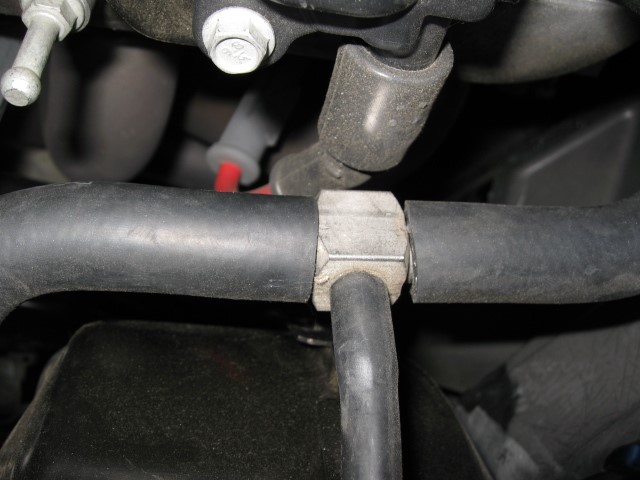
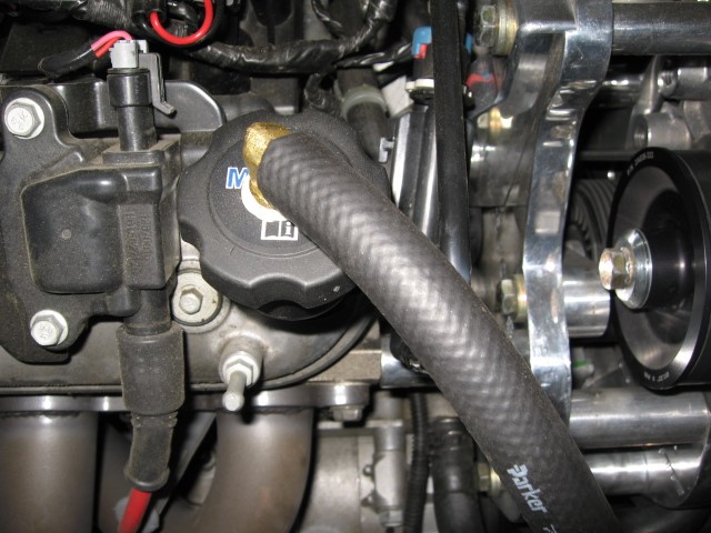
The preferred method of draining the oil from the supercharger to the sump is by cutting and tapping a 3/8” pipe fitting directly into the front of the oil pan.


  • Locate and center punch the hole approximately .400” from the bottom of the pan and as far over to the right as possible. Drill a 1/8” pilot hole. Use the supplied 9/16” Rotabroach (very small hole saw) to cut through the pan. Be very careful as you break through the pan. You may even be able to drill until there is just a paper- thin amount of aluminum left and actually pop the disc of aluminum out. The Rotabroach will allow you to drill a large hole with little or no aluminum chips.

(OIL PAN PILOT HOLE AND AFTER CUT WITH ROTOBROACH)

  • Take a 3/8” NPT tap (not included) and fill the flutes with heavy grease to catch any chips. Tap the hole a little, then remove and clean the tap of shavings. Put more grease on the tap and do it again. Most 3/8” NPT taps use a 9/16” square drive. (measure yours to be sure) A square socket on an extension will make the tapping process very easy. Tap the hole approximately 1/2”deep or until the brass fitting will just start. Be careful not to go too deep. The oil pickup screen is very close to this location and can be damaged if you are not careful. Clean up any stray chips. Drain the engine oil and install a new oil filter. Clean the threads and fitting with carburetor cleaner or something similar and apply a small amount of silicone sealer to the pan threads as well as the threads on the 3/8” NPT to ½ barbed fitting. Make sure there is a seal formed all around the fitting. There is plenty of aluminum to form threads in the pan. Oil leakage at the fitting is a non- issue. Attach the drain hose to the fitting and tighten with a clamp. Run the hose up towards the area where the supercharger will be mounted.

(OIL DRAIN FITTING INSTALLED IN OIL PAN)

INSTALLING THE OIL FEED LINE

  • The oil feed line is attached at the lower drivers side of the block. Remove the galley plug with a 5/16” allen wrench and replace it with the provided fitting AND sealing washer.

  • Screw the line onto the fitting and route it up to the supercharger at the other end. Route it behind the steel hose that comes out of the bottom of the power steering pump, over the rubber hose on the power steering reservoir and through the hole in the reservoir bracket. This will assure the line won’t interfere with the belt. Run the line under the throttle body to the passenger side of the car where it will be later attached to the supercharger unit.

   (OIL FEED LINE AND FITTING LOCATION AND OIL LINE ROUTING)

(LINE RUNS THROUGH P/S RESERVOIR BRACKET AND UNDER THROTTLE BODY)
(SUPERCHARGER NOT INSTALLED AT THIS POINT. FOR LOCATION REFERENCE)

REINSTALL THE STEERING RACK AND ABS MODULE

  • Move the rack back into position. Install the 18MM bolt on the passenger side loosely. Reinstall the ABS module and bracket. Remember to make sure the flats machined into the rubber mounted studs are aligned vertically with the slots in the bracket. Install the remaining 18MM bolt through the ABS bracket and steering rack and tighten. Reinstall fan assembly and trim upper fan shroud as shown. (The radiator will be trimmed later in the installation)

(RADIATOR FAN SHROUD TRIMMED)

RELOCATING THE LOWER RADIATOR SUPPORT/ SKIDBAR ASSEMBLY

  • Remove the (4) 10mm bolts holding the air dam to the radiator support bracket. Save these bolts as you will be using two of them later in the installation. Carefully cut out the springs and take the metal brackets off the plastic air dam. You will be reinstalling the air dam with hardware supplied in the kit.

(REMOVE FOUR 10mm BOLTS HOLDING THE AIR DAM)

  • Attach the L brackets supplied in the kit to the air dam using the existing holes. Hold the air dam up to the bottom bar of the support bracket. Mark holes and then drill ¼’ holes all the way through the bar. Attach the air dam with the supplied hardware. Once the air dam is secure, bend it down to an optimal angle for the air to flow up to the radiator area.

(AIR DAM RE-ATTACHED)

(BEND AIR DAM DOWN TO OPTIMAL ANGLE)

  • Remove the (5) 7mm screws that hold the bottom plastic shroud on the passenger side in front of the tire. Remove the plastic piece and set aside, this gives you access to the horns and the passenger side radiator support. Remove the 10mm bolt that holds the horn bracket to the radiator support. Disconnect the horns and remove from the vehicle. On the driver side, remove the same 7mm screws and remove the panel. 
  • Flatten the little 90° bend on the horn bracket. Drill out the mounting hole on the horn bracket with a 21/64” bit. Pick up the horns and look at the way they are pointed. Then, remove the nuts holding the horns and swap them, keeping the horn orientation the same and fasten. This gives more room to connect the harness to the horns. You want to make sure they end u facing down or slightly down so they can’t fill up with water. 


  • Remove the 13mm bolts that hold the skid bar to the frame on passenger side but just loosen them on the driver side. Insert the short spacer between the assembly and the frame at the front attachment point, put the hole on the horn bracket on top of the spacer and insert the new 8 x 50mm bolt. Insert the long spacer at the rear attachment point with the 8 x 50mm bolt. Leave the bolts loose for now. Attach the two spacers on the driver side before tightening all 4 bolts. The horn bracket can be bent if needed to clear the brake duct.

(FRONT VIEW OF RADIATOR SUPPORT MOUNTING POINTS WITH HORN BRACKET)

  • Drill a ¼” hole in the front vertical bar for the outside air temp sensor. Use the factory push pin and fasten the sensor to the radiator support.
  • In the open compartment on the driver side where you removed the plastic shroud, you should see the air injection pump. There is a break in the air hose going from the air pump up to the stock air filter about half way up the front of the air shroud, disconnect the hose here and insert the new filter , then route into the area next to the air pump. Then you can put the driver side compartment back together.

(DRIVER SIDE FRONT WHEEL WELL COMPARTMENT)

MOUNT THE REAR SUPERCHARGER SUPPORT BRACKET

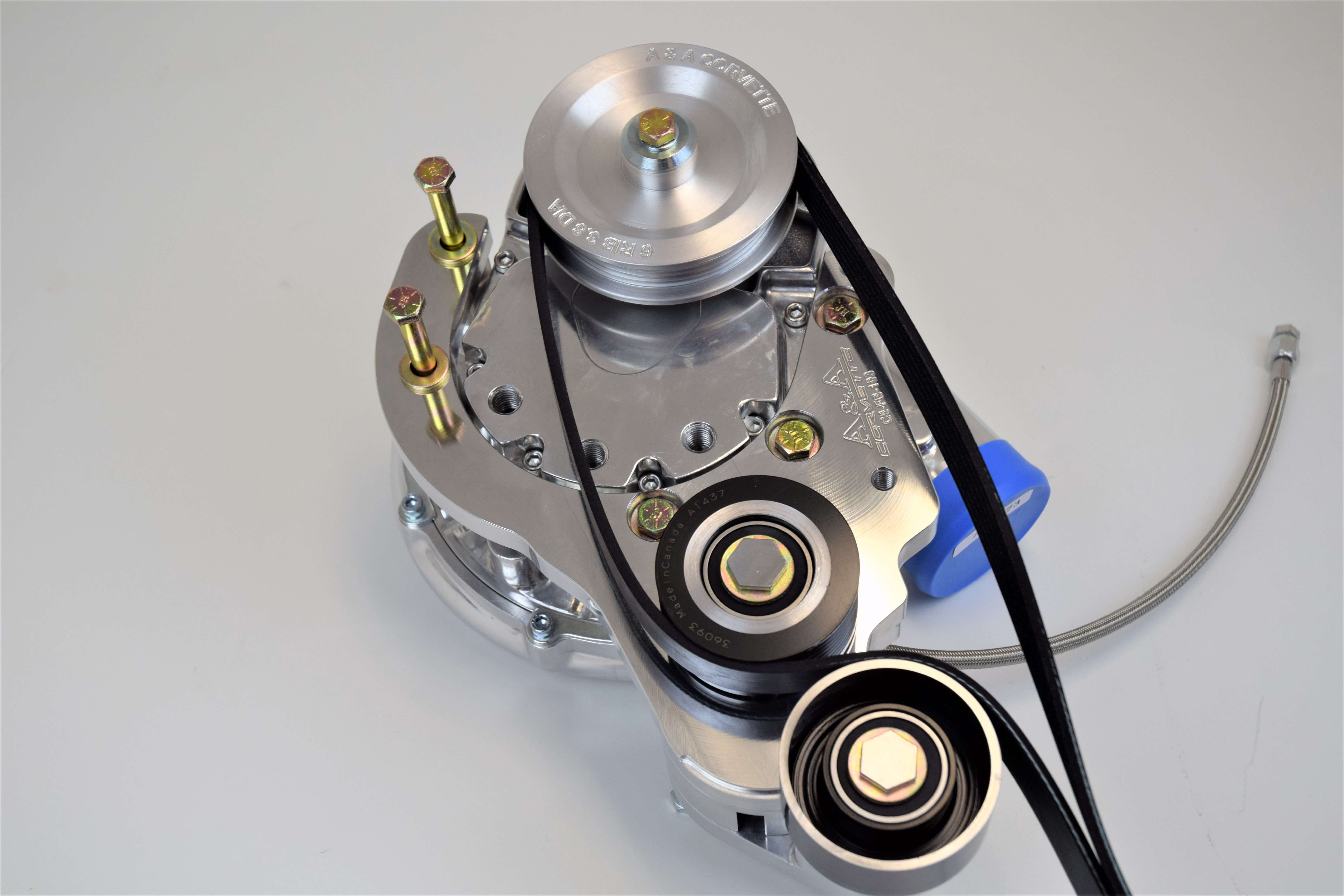
The rear bracket comes with the adjustable idler attached. We do this to make it easier for the installer to understand how the bracket assembly works. Remember how the sliding idler is attached, remove it and set aside. You will reinstall this after the main supercharger bracket is installed.


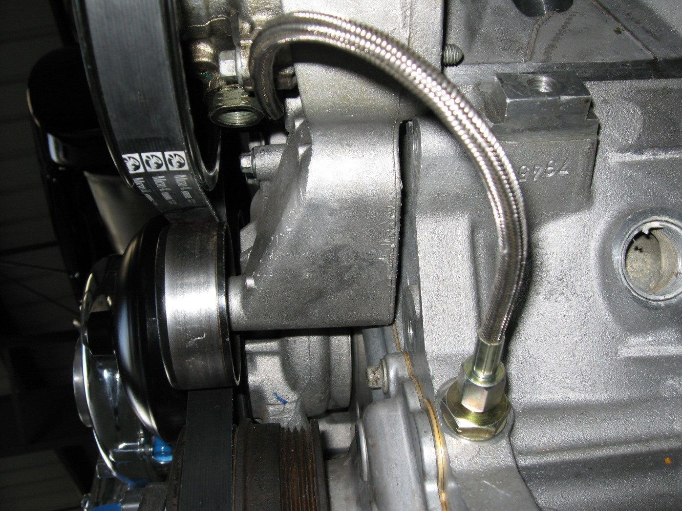
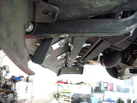
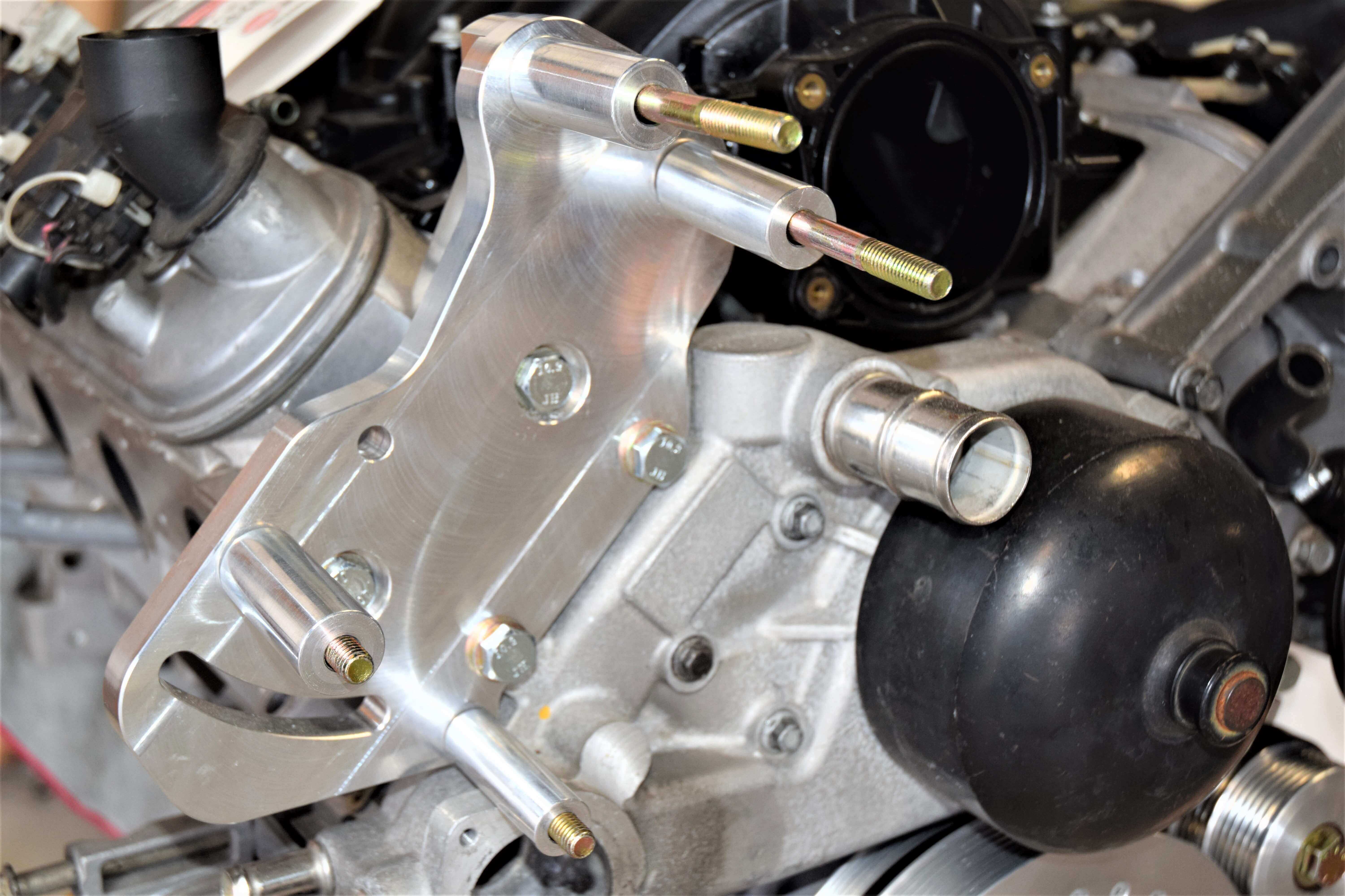
The rear bracket bolts to the water pump, using the (2) stock tensioner bolts and holes. It also bolts to the cylinder head with the M10x90mm bolts, a 2.460” spacer and the thick angle brace. Make sure you use a THIN washer on the M10 bolt that goes through the bracket and round spacer to the cylinder head. It’s also important to install the lower of the 2 long bolts that attach the supercharger/main bracket assembly through the rear bracket before mounting it to the engine. The intake manifold or cylinder head will not allow them to be installed afterwards. The spacer closest to the water pump is ¾” in diameter.

 REAR BRACKET - ATTACHED TO ENGINE

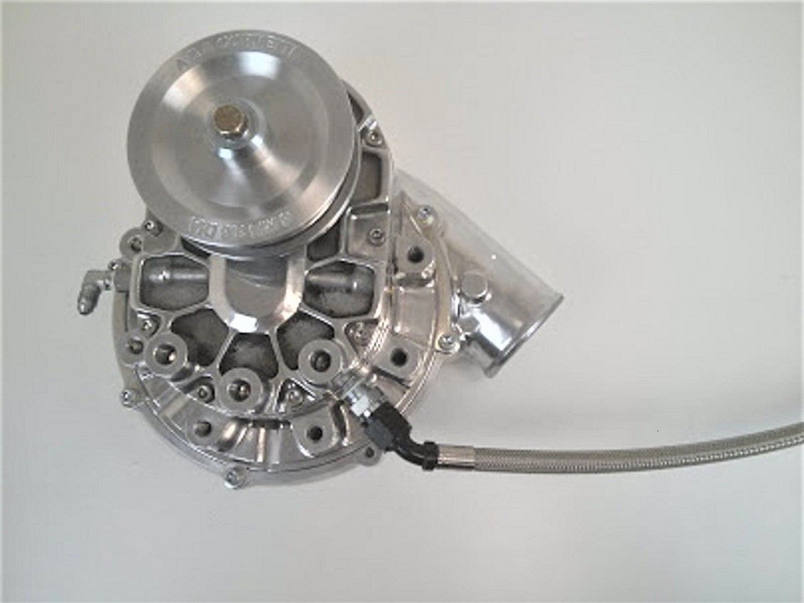
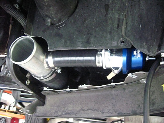
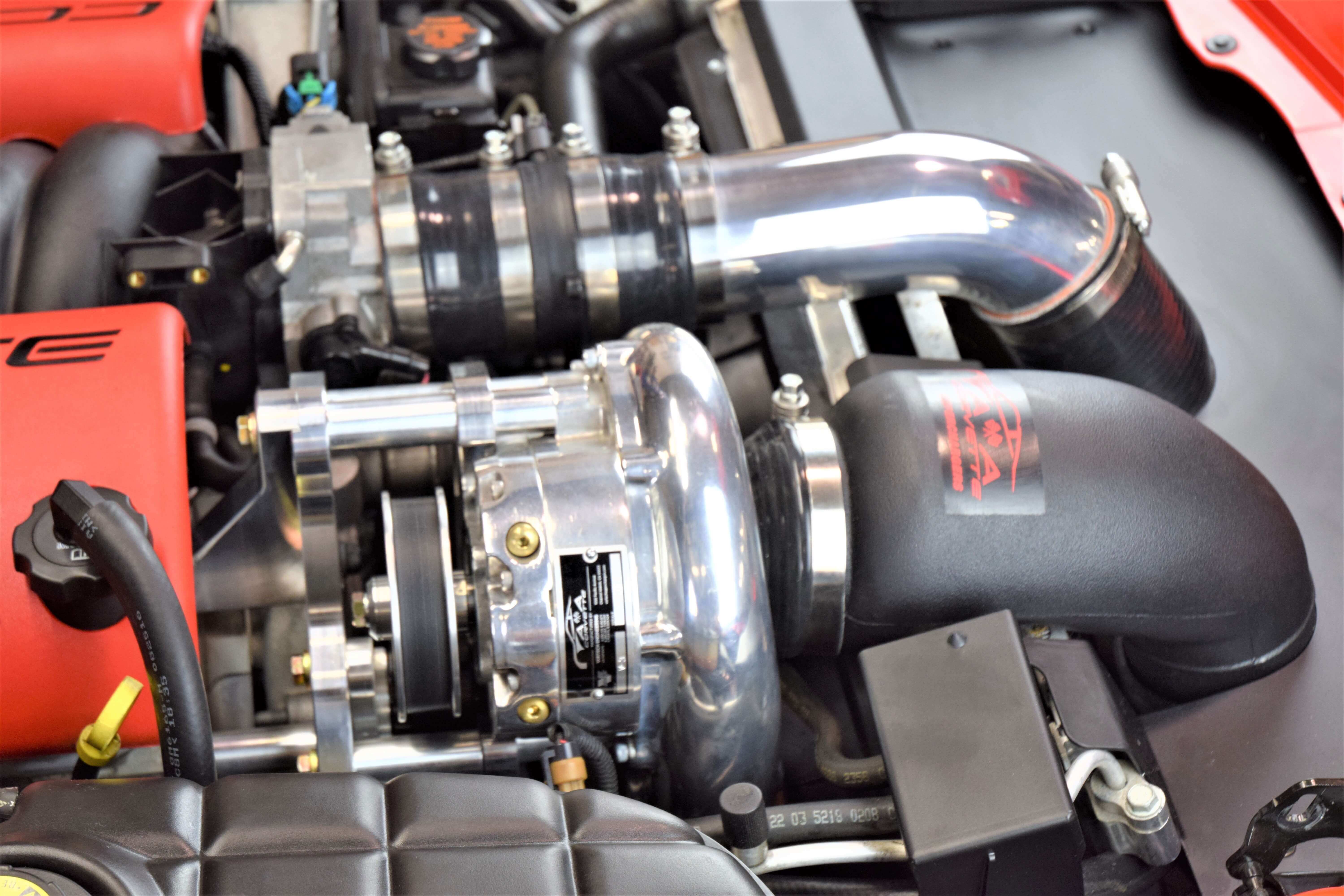
On V1, V2, and V7 models ONLY, you will need to connect the oil drain line to the supercharger before mounting it to the bracket. We use stainless AN line and it is extremely tight in this area. The line MUST be oriented as shown in the picture to avoid contact with the tensioner. Double check this clearance after the installation is complete.

AN LINE ATTACHED TO BLOWER

MOUNT SUPERCHARGER TO MAIN BRACKET

  • Locate the 1.160” aluminum spacers with the flat sides. These will space the supercharger from the main bracket. Place the spacers on the supercharger with the flat sides facing the supercharger and bolt the bracket to the supercharger with the 2 ½” bolts and spacers as shown. You’ll notice in the picture that 3 bolts are tight up against the bracket. The other 2 longer bolts are only there to assist in keeping the remaining 2 spacers aligned while you’re tightening the 3 shorter bolts. Once they are tight, you can remove the other 2. 


  • The billet tensioner has an open 5/16” hole on the front. While having someone hold the bracket assembly, rotate the tensioner clockwise, using a ¾” socket, until you can push the lock pin (5/16” bolt) all the way in the hole. This locks the tensioner open and ready for belt installation. (NEVER take out the black socket head bolt)

BRACKET MOUNTED WITH TENSIONER LOCKED IN THE SLACK POSITION WITH BELT LOOSELY ROUTED AROUND THE PULLEYS

  • Look at the belt routing diagram before mounting the blower and routing the belt. It’s just a good idea to have a visual image in your head of how it’s going to run. We also put the belt on in the previous picture just for a visual reference.
  • Install the drive belt in the vehicle. Wrap the belt around the crank pulley, up and over the idler, down to the power steering pump and up towards the alternator, but do not wrap around the alternator pulley yet. This will leave you with a large loop on the passenger side. Loop the belt between the spring tensioner and the ribbed idler pulley and then around the supercharger pulley as in the previous picture. Lower the bracket into place. The long bolt coming through the rear bracket and spacer is probably the easiest to start. Thread this bolt into the supercharger a few turns to take the weight.
  • Double check the belt as it comes off the spring tensioner. It should go down and under the balancer. If the belt is routed correctly, try to align the front and rear brackets and get the remainder of the 3/8” bolts started. Once all 4 bolts are in, tighten them up just snug them up to make sure the blower is in its final position. You can now pop the belt over the alternator pulley. 


  • You’re going to temporarily remove the outside spacer and bolt for this next step. Reinstall the sliding idler on the “J” shaped bracket as it was when the unit was shipped.

PROPER BELT TENSIONING PROCEDURE

  • Make sure the spring tensioner is locked in the open position. (Rotated clockwise with the5/16” lock pin inserted) Rotate the sliding idler, located just below the blower pulley to the inboard side with a 9/16 wrench on the exposed bolt. This is a left- handed thread so you will not loosen the bolt while pulling down. The belt does not need to be extremely tight. (On super high horsepower applications, you will want to make the belt very tight at this point) Remember that the spring tensioner is still in the open position. Pull down on the wrench and then tighten the two bolts on the bracket. Reinstall the outboard spacer and bolt that you just removed. Tighten all 4 bolts going to the supercharger bracket. Now you can go to the spring tensioner and remove the lock pin to properly tension the belt. You’ll need to rotate the tensioner slightly to take the load off the pin.

ADJUSTING THE SLIDING IDLER

  • Make sure the drain line does not interfere with the tensioner. Tie it off to the side if it does.

CRANKCASE VENTILATION

  • Attach (2) vacuum caps to the throttle body and the valve cover where the breather hose was previously located.


  • Check valve. If your vehicle has a PCV valve off the manifold, you will NOT need to use the supplied check valve. For the vehicles that have a loop off the intake manifold to the valley cover with no PCV valve, you will need to replace it with the supplied hose and check valve. Make sure the arrow is pointing towards the intake manifold.


  • Remove the oil filler cap from the passenger side valve cover. Using a 9/16” drill bit or supplied Rotabroach, (supplied with oil fed systems only) drill a hole in the top of the cap and tap the hole with a 3/8” NPT tap. Screw the provided 90 degree plastic fitting into the top of the cap (a small amount of silicone sealer is advised) and reinstall the cap.


  • The 5/8” hose that is coming up from your air filter is attached to this nipple. Orient the hose and nipple so that there is enough slack so that you can remove and install the cap without having to remove the hose or rotate the fitting We have found that venting the crankcase from this area is much less likely to push oil out with the vapors, eliminating the need for a catch can, in most applications.

CAP WITH FITTING INSTALLED

REPLACEMENT HOSE WITH CHECK VALVE 

TRIMMING THE RADIATOR AND FAN SHROUD

  • The upper “fins” on the radiator will need to be trimmed for clearance. This can be done in the vehicle. A jigsaw, die grinder or even a hacksaw can be used. The fan housing must also be trimmed in the upper corner just under the supercharger inlet to allow the inlet duct to attach to the supercharger. Put the duct in place without the silicone coupler to determine how much trimming will be needed. Leave the blue cap on the supercharger inlet and cover the throttle body.

(RADIATOR MARKED FOR TRIMMING)

(RADIATOR TRIMMED FOR INLET DUCT CLEARANCE)

  • Clamp the 2.75” to 3” silicone reducer to the 3” X 6” aluminum tube. ( YSi head units use a straight 3” coupler) Slip another clamp loosely over the top of the reducer. Orient the clamp so it is facing towards the frame rail and slightly back. This way you will be able to get at the clamp from the top when standing next to the car. Slip the coupler over the blower outlet and tighten the upper clamp.

  • The remainder of the plumbing as shown in the picture below will be installed later. 
  • The sheet metal panels will now be installed. Attach the metal mounting clips that were removed earlier to the big sheet metal panel. that the large panel will use the (2) 10mm bolts removed previously, to attach the top two holes in the large panel to the frame, use the holes that the stock air box plugged into. You will need to tuck the 90* bend behind the front plate before putting the 7MM screws through the bumper and front plate.

(DRIVER SIDE PANEL ATTACHED)

  • Attach the front bumper lip the to the large panel with (5) 7mm screws previously removed.

  • There are 2 holes pre-drilled in the front panel. Line the side panels up on either side and use self- tapping screws through these holes. Add another self-tapping screw on each panel and attach them to the frame of the vehicle.

(PASSENGER SIDE PANEL INSTALLED)

INTERCOOLER INSTALLATION

  • The intercooler will go in next. The remainder of the tubing and the BOV will go in after the intercooler is mounted. Attach the large “L” brackets to the top of intercooler with the supplied bolts and washers, leave loose. (The long leg goes on the cooler) Push the cooler up from the bottom. Make sure the intercooler is horizontal with the exit tube lined up with the throttle body. The weld between the top tank and the core is to be oriented so that it is even with the bottom of the frame. The side fins on the intercooler should be flush with the front panel to seal in airflow. The inlet will go IN FRONT of the upright skid bar support. Once the intercooler is aligned properly, mark mounting locations on the frame. Use a 1/8” drill bit to make pilot holes on the frame. Attach the intercooler brackets with the supplied self- tapping screws.

(INTERCOOLER ATTACHED WITH MOUNTING BRACKETS)

  • Using one of the 7 MM corner screws mount the small “L” brackets at each corner of the intercooler. Once you have the brackets lined up, attach them to the intercooler side fins using the provided self-tapping screws.

INTERCOOLER LOWER BRACKETS INSTALLED


  • Attach the duck bill to the front of the intercooler with the 4 stainless button head bolts, nuts and washers provided. Be sure to use anti-sieze on these to prevent them from locking up.  

(DUCKBILL ATTACHED TO INTERCOOLER)

  • Attach the Custom 90° hose to the inlet of the intercooler and clamp down. This hose has some small bends to get up and over the skid bar. Mark the front panel in front of the passenger side front tire for trimming. The panels will be trimmed to allow the long silicone hose to go forward into the right front fender cavity. You will be cutting off one mounting hole, so you will need to drill a new hole to attach the metal clip and 7mm screw to.

(FIBERGLASS PANEL MARKED)

  • Attach the blowoff valve (BOV) and 2” silicone coupler to the 6” metal tube with nipple. Attach the tube to the end of the custom silicone hose going to the intercooler. The BOV should be aligned so that the hose goes under the front brake duct and the filter points forward as shown. You may need to heat the plastic duct to make a dimple in it for clearance. Attach the supplied vacuum hose to the blowoff valve and run it back through the fender cavity under the driver side fan and up between the two radiator fans (there is a notch between them). It will be “teed” in to the power brake booster hose in a later step. Make sure the hose is tied up and away from any moving parts.

(BOV PLACEMENT)

  • You can now install the long silicone charge hose. Clamp it to the 6” tube coming down from the blower outlet and to the BOV tube. It will go behind the sway bar. You may need to slightly tweak the AC and transmission cooler lines for clearance. Refer to the picture shown earlier for a visual reference as to how it should be installed.


  • Line up bottom plastic panel and mark it to be trimmed. After it is trimmed, drill a ¼” hole about one inch in from the left. This will be the mounting point that was cut off when the panels were trimmed.

(BOTTOM PANEL MARKED)

  • Attach the bottom panel and verify clearance of the tubing.

(MOUNTING HOLE MOVED)

  • If you have a 2001-2004 model, you will need to TRIM a small tab on the MAF to allow the silicone sleeve to go all the way on the flange.

TRIM SMALL TAB OFF

  • The outlet from the intercooler should be centered and in line with the throttle body. Install the 3 ½” silicone “S” coupler, the 60° mandrel bent tube, another silicone coupler, the MAF and then another silicone coupler to complete the connection between the intercooler and throttle body. The silicone coupler at the throttle body will be very tight but it WILL stretch over the throttle body. The use of a hose hook will make it much easier to slip the hose over the large end of the MAF and the throttle body. 

  • NOTE: (If you have a 1997-2000 model, mark the 60° aluminum tube on the driver side and drill a 5/8” hole. Insert the grommet from the IAT sensor and install the sensor).
  • Align all the ducting and tighten all the clamps

INSTALL THE AIR BRIDGE

  • Slip the plastic air bridge over the radiator in front of the supercharger. Check to see if the plastic fan shroud will need any trimming. Trim as needed. 


  • Clamp the 4 ½ “reducer on the supercharger inlet. Install the supplied air filter onto the formed air bridge. The air bridge will go over the top of the radiator and slip into the large end of this coupler.


  • (You will really benefit from the use of a hose hook in this extremely tight area) Check the area around the fan shroud where you trimmed earlier to make sure enough material was removed.

(AIR BRIDGE INSTALLED)

  • Install the threaded barbed fitting into the hole in the air filter. It is very tight but the fitting will go in the hole in the filter flange. Attach the supplied 5/8” vent hose to the nipple. Route the hose up towards the valve cover. You will be attaching this hose to the oil fill cap later.

TOP COVER INSTALLATION

  • Find the two laser cut mounting brackets. Install them on the frame rails using the supplied self- tapping screws as shown. You’ll notice that the bracket is offset to conform with the frame. Make sure the top of the bracket is even with the top of the frame rail. There are two holes it the top cover as well. Make sure the mounting bracket will be located under these holes.

MOUNTING BRACKETS INSTALLED

  • Lay the top shroud on the brackets making sure the front tucks into the seam where the front bumper meets the frame. Attach the shroud to the brackets using the supplied black 7MM screws. You will need to pre-drill the bracket with a 1/8” drill bit using the top shroud as a guide. There is a notch on the passenger side for the hood light wiring loom to go through.


  • The two upper support brackets bolt through the existing holes using your original bolts. Remove the rubber snubbers from your original support and install them in the new steel ones.

TOP SHROUD, UPPER SUPPORT BRACKETS AND DUCTWORK INSTALLED

  • Find the power brake booster hose and cut it in the middle. This is where the provided stainless vacuum “T” will be installed. Run a short piece of vacuum hose over the power brake booster to get your vacuum fittings away from the heat. We have provided a couple of nylon “Y” fittings to hook up the BOV, boost gauge, Boost a Pump and any other accessories that may be vacuum or boost operated.

(STAINLESS “T” INSTALLED IN BRAKE BOOSTER HOSE)
(Note vacuum hose routed over the booster, away from the heat)

(OIL CAP VENT)

FUEL PUMP INSTALLATION (1997 to Early 2003 Models prior to VIN# 114930)

  • It is much easier and safer to have as little fuel as possible in the tank when changing the fuel pump. Observe all common- sense safety precautions. Have a suitable container and a large mouthed funnel to catch the fuel. Keep any source of sparks or heat away and be aware of vapors, which can be explosive. Double check that the battery is disconnected.


  •  Remove rear driver side wheel. Remove the 10mm nut and 13mm bolt holding the access panel.


(REMOVE ACCESS PLATE)

  • Remove the (4) 13mm nuts holding the gas tank protection/hold up plate. The tank will drop only slightly, if at all, with a light fuel load

(REMOVE PROTECTION/HOLD UP PLATE)

  • Place a suitable container under the access panel as fuel will spill out. A large tub works best. Unplug the harness; squeeze the clear plastic tabs to disconnect the fuel lines. Remember the configuration. Remove the five of the six ) 7mm bolts and loosen the top one. Carefully let the bottom of the panel separate from the tank and let the fuel spill into your container. Loosen the remaining bolt more ,or remove it completely when the fuel flow slows and you’re comfortable doing so.
  • Pull the canister partially out and you will see the fuel level sensor arm. Remove the black clip holding the arm and set aside. Gently pull the metal arm off the white plastic connector. Remove the arm, noting how it was positioned in the tank, and set it aside. Take out the fuel bucket assembly.
  • There are three tabs that hold the lid on the fuel canister. You will need to pry the lid open while pushing in on the tabs.
  • Attach cap on the new fuel pump bucket and then install the whole assembly back in the car in the reverse order it was removed.


  • You must pay particular attention to the float arm and the fuel hose. Make sure the fuel hose does not interfere with the float arm throughout its travel.

BOOST-A-PUMP INSTALLATION (For late 2002 and up C5s)

  • Remove the Boost A Pump (BAP) from the package and locate the long wire harness with the gold RCA plug on the end. Cut the harness close to the BAP, strip the two wires inside and twist them together. (if this has not already been done) Solder or use a butt connector and tape the ends up to prevent grounding. Throw the adjuster box away! The reason for doing this is to assure that the BAP is not accidently turned down or the plug is not pulled from the rheostat while cleaning the car, etc.

  • Raise the car on a suitable lift or jack stands.

  • Disconnect the battery.

  • Remove the left rear wheel and inner wheel well liner. The liner is attached with 7MM screws.

  • The BAP will be bolted to the bulkhead in front of the wheel. Mount it as far to the left as possible to allow adequate clearance for the wheel well liner. You will find that the bulkhead is curved and only 3 screws will fit.


BAP LOCATION

  • Locate the wire harness for the fuel pump. The later 03+ cars have the wire harness at the top of the bulkhead where you are going to mount the BAP. The 97 to early 03 cars have the harness down by the fuel pump canister. To get to this harness you need to take the aluminum inspection plate off. The large gray wire is the fuel pump power lead. Cut that wire and strip both ends (some model years may have two gray wires, cut the one at the end of the plug as shown below) . The hot end of the wire (the end that comes from the front of the car) is soldered (or butt connected) to the red wire with the fuse holder on the BAP. The other end (the end that goes to the fuel pump) is soldered (or butt connected) to the other red wire on the BAP.


(late C5 and C6 harness location)

(early C5 harness location)

  • The black wire is grounded to the frame near the BAP. Crimp or solder the ring connector to the wire, grind some paint off the metal and attach it with a self-tapping screw.

  • 14.8 The remaining wire harness contains two wires. These wires will be attached to the boost pressure switch and are fished through the rocker panel up to the front of the car. Remove the small access panel behind the front wheel, push a metal tape measure through the rocker panel until it comes out by the rear wheel. Tape the wires to the tape measure and pull it back and out through the front.

(Pressure switch wires running through the rear rocker panel)

 (Pressure switch wires running through the front rocker panel)

  • Run the wire up to the power brake booster area. Install two female spade connectors to the wires. Find the boost switch in the package. Screw the barbed fitting onto the switch using a small amount of pipe sealer. Plug the two wires onto the boost switch. (Polarity does not matter) The barbed fitting is “teed” into the brake booster hose with a piece of vacuum hose. Boost pressure closes the switch and activates the BAP at approx. 3-4PSI

FINAL ASSEMBLY AND CHECK

  • FINAL ASSEMBLY AND CHECK 

  • Refill engine with fresh factory specified oil.

  • Check all fittings, nuts, bolts and clamps for tightness.

  • Reconnect the battery.

  • “Key on” (DO NOT START) the vehicle to cycle the fuel pump. Do this a few times as the pump only comes on for a few seconds if the engine does not start. Ensure that the fuel rail and injectors are sealed properly.

  • If vehicle PCM has been flashed for the injector change, start vehicle.

  • Recheck all fluid levels and verify that no hoses, wires, etc. are near exhaust headers or moving parts and that there is no fluid leakage.

  • The passenger side coil cover will need to be trimmed to fit over part of the supercharger mounting bracket. Trim as shown in photos and the reinstall both plastic coil covers

(PASSENGER SIDE COIL COVER TRIMMED)

(TRIMMED PASSENGER SIDE COIL COVER INSTALLED)

(V3 models remove the shipping plug and install vent as shown)

PULLEY AND BELT SIZE CHART 6-RIB


K060900K060905K060910K060915
3.40”BEST FITFITS

3.60"
BEST FITFITS
3.80"

BEST FITFITS
4.00"


BEST FIT

PULLEY AND BELT SIZE CHART 8-RIB & 8” BALANCER


K080903K080910K080922K080939
3.125”FITSFITS

3.33"
FITSFITS
3.47"

FITS
3.60"

FITS
3.80"

FITSFITS
4.00"

FITSFITS

SUPERIOR CUSTOMER SERVICE BEFORE AND AFTER THE SALE

We want you to have the best experience possible when dealing with us both before and after the sale. You can always talk to a sales manager, the owner and head designer, or one of our techs who is infinitely knowledgeable on how the products operate and are installed. You won’t get a minimum wage customer service rep that knows nothing outside his or her script. You’ll get great advice based on many years of experience every time.


We’re happy to help you with your DIY install questions or product inquiries even after hours. The phones forward to either a Manager or Owner to help with both. Remembering that we are on Pacific time, you can generally get help until 9PM on weekdays and weekends alike. It’s something we started when the company was very young and have found it to be an invaluable resource to our customers.


TERMS & CONDITIONS


WARRANTY INFORMATION


PRIVACY POLICY

SHARE THIS PAGE!